
Every Smart City needs to plan and implement a highly resilient and effective communication network for connecting CCTV Cameras, ICT Networks etc for which Dark Fiber is to be laid across the City. Here are the guiding principles for designing a Transport Network using Multiprotocol Label Switching (MPLS) to construct a packet switched transport network.
Business requirements:
Technical Design requirement:
Following are the major design requirements captured for IP/MPLS transport network:
The transport underlay of the Core ring network (100G) shall be based upon MPLS data plane with Segment Routing (SR) capabilities provided by the ISIS routing domain. Segment Routing technology will distribute the segment (labels) for node and adjacency no other signalling protocol will be used (LDP or RSVP for label generation). BGP is enabled for overlay technologies such as L3VPN, EVPN and mVPN. Topology Independent Loop Free Alternate (TI-LFA) is enabled in the underlay network to achieve the highest degree of resilience and service availability. Network level and service level QoS is deployed on all nodes to ensure the expected behaviour of packet delivery in the event of network congestion.
Network overlays provide the ability to enable new services with a high degree of transparency and decoupling from the underlay network. EVPN, MVPN and IP Access are leveraging Multi-Protocol BGP (MP-BGP) as underlay network. IPv6 will be served as overlay over the IPv4 MPLS based underlay network. To transport IPv6 packets over IPv4 underlay, 6PE and 6VPE will be deployed. There is no requirement for IPv6 based mVPN. Ethernet OAM is used to monitor the network and service components level.
Core Routing:
Choose ISIS as IGP protocol for MPLS core network. ISIS (Intermediate System-to- Intermediate System protocol) is a link state protocol and is very popular and most of service providers are using in their core. The convergence time of IS-IS protocol is very fast and it can easily be scaled in large networks. It is also a very flexible protocol and has been prolonged to incorporate important superiority features such as MPLS (Multi-Protocol Label Switching). The basic features of the IS-IS protocol remain same as OSPF, however; it provides some additional features that are missing by the OSPF protocol.
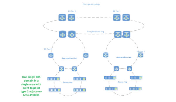
IS-IS as the Interior Gateway Protocol (IGP). IS-IS is a link-state routing protocol which provides flexibility to integrate new features such as IPv6 and Segment Routing. Having a flat L2 IS-IS network is an added benefit for Traffic Engineering (TE) and flexible Segment Routing Mapping distribution. Running TE tunnels across multiple ISIS levels/domains invites more challenges to the design (SR mapping server advertisements do not propagate ISIS areas and possible route leaking to get end-to- end IGP info are some of them), hence the decision for a flat L2 IS-IS design.
All core, aggregation and access provider core routers will run ISIS with Type 2 adjacency in same area
Use of BFD for reducing Failure detection time Use NSR for ISIS for nonstop routing
ISIS has enhanced capabilities due to TLV support and has advanced features like maintenance mode (overload bit), This functionality is useful to Service Providers (ISPs) who run both Border Gateway Protocol (BGP) and IS-IS to avoid a couple of "black hole" scenarios. Setting the overload bit for a fixed amount of time right after a reload ensures that the router does not receive transit traffic while the routing protocol is still converging.
IP / MPLS / Segment routing:
SR is a source routing based tunnelling technique that allows a host or an edge router to steer a packet through the network by using a list of segments, instructing how devices should process the packet. Segments can refer to the instruction of sending a packet over the shortest path to a node, over a specific link, or towards an application. Because the information of the path that the packet must traverse is included in the packet, intermediate routers do not have to maintain state for all possible paths that the network offers. Additionally, because a shortest-path segment includes all the ECMP paths to the related node, SR supports the ECMP nature of IP by design. These two features provide drastic gains in network scalability when compared with traditional methods of traffic-engineering such as RSVP.
The data plane of SR defines how to encode the sequence of segments to be applied on a packet, and the forwarding semantics of segments (i.e. how each device should process a packet based on a segment). MPLS will be used as data plane for SR in MPLS network. All nodes in the MPLS network supports SR data-plane operations (such as Continue, push and next).
The control plane of SR defines how the segment ID information is communicated among devices in the network. In the MPLS SR network, segment identifiers are advertised via the ISIS protocol. ISIS has been extended to support the distribution of segment IDs. Each node running ISIS with SR feature enabled maintain a database of all nodes and adjacency segments.
SR in MPLS Network uses Prefix-SID and Adjacency SID that direct the data along a specified path. Prefix SID are globally unique. Loopback address is encoded in a specific type of Prefix SID called Node SID (By default, the N-flag is set on each configured Prefix-SID, hence all prefix IDs are node ID in IOS-XR). Adjacency SIDs contains the advertising router’s adjacency to a neighbour, it is locally significant.
SR for ISIS implements all interfaces for MPLS no need for separate signalling protocol (LDP or RSVP). Default Segment routing global block – 16000 to 23999 (8000 number of labels)
Prefix SID (Node Identifier) will be chosen from Last octet of Loopback0 IP address
This label mechanism by enabling Segment Routing will allow traffic for label switched between PE’s. Other design characteristics are listed below:
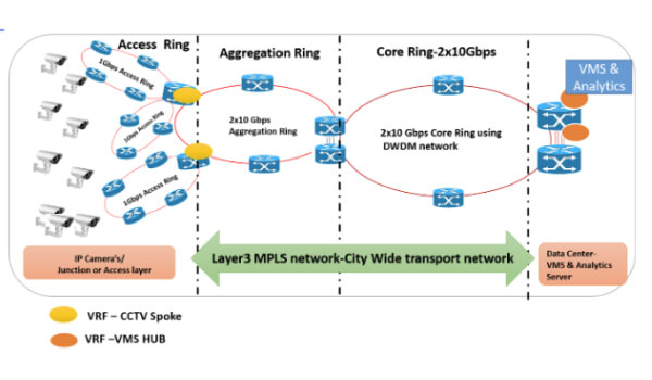
City Wide Transport network will be deployed using IP/MPLS technology and will be service independent and will be used for carrying services like CCTV Based City Surveillance, Vehicle detector based Adaptive Traffic Control System and various other ICT based services for smart city initiatives.
MPLS network will offer below mentioned services:
Layer 3 MPLS VPN:
A Multiprotocol Label Switching (MPLS) Layer 3 Virtual Private Network (VPN) consists of a set of sites that are interconnected by means of an MPLS provider core network.
2 VRF’s will be used for L3VPN network
CCTV VRF:
VMS VRF:
L2VPN / EVPN:
The multipoint EVPN service is an extension of the point-to-point EVPN VPWS service. For the multipoint support it adds the Ethernet MAC address learning vi the MP-BGP protocol and enables multiple sites to be connected to one logical Ethernet L2 bridge domain.
The same circuit options as for the p2p EVPN are supported and the BGP EVPN service will create a logical full mesh between all Routers which connect to a service endpoint directly, via star access.
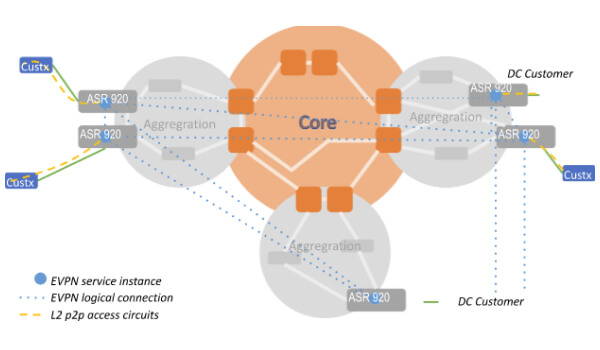
Ethernet VPN service based on IETF BGP EVPN
BGP Design:
Hierarchy Route Reflector:
Route reflector is the preferred method to achieve BGP scaling in network. A BGP route reflector is an IBGP speaker that reflects or repeats routes learned from IBGP peers to some of its other IBGP peer.
To prevent loops, a route reflector adds an originator ID and a cluster list to routes that it reflects between IBGP speakers. These attributes act similarly to the autonomous system path attribute to prevent routing information loops.
All configuration of the route reflector is done on the route reflector itself. The configuration identifies which IBGP peers are route reflector clients. Implementing route reflectors is fairly simple and can be done incrementally. Each client router needs to be configured as a client on the route reflector or on multiple route reflectors.
Often, route reflector clients peer only with the route reflectors. To avoid a single point of failure, redundant route reflectors are typically used.
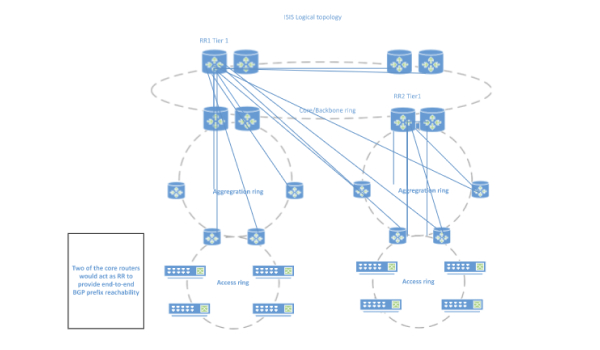
In the proposed City Network solution, it is recommended to have a Hierarchical BGP Route Reflector design.
All Routers including Core, Core at Pop and Aggregation will be connected to Central Route- Reflectors. All these routers will be running labelled BGP. All these routers will be running IBGP with Route Reflector for sharing their LAN (VPN) routes.
Multicast VPN:
Multicast VPN (MVPN) is deployed in the IP network in order to support IP Multicast IPVPN services. MVPN implementation is based on version 6 of “draft-rosen”1 and requires native IP Multicast support in the IP core: PIM-SM is used in the IP core to build the Default Multicast Distribution Tree (MDT) with Rendezvous Points (RP) configured in all core routers as well as in some selected Aggregation ones (with anycast IP address and MSDP full-mesh configured in all RPs). PIM-SSM is used in the IP Core to build the Data MDT for high traffic rate sources. Finally, GRE IP tunnelling is used in the core to transport customer multicast traffic. In the customer domain, PIM-SM run
between CPE and access router, with RP configured in the Hub site CPE. Below figure shows the Multicast VPN protocol architecture.
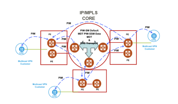
“Draft-Rosen” Multicast VPN Protocol Architecture
MPLS Traffic Engineering capabilities:
Enhances standard IGPs, such as IS-IS or OSPF, to automatically map packets onto the appropriate traffic flows.
Transports traffic flows across a network using MPLS forwarding.
Determines the routes for traffic flows across a network based on the resources the traffic flow requires and the resources available in the network.
Employs "constraint-based routing," in which the path for a traffic flow is the shortest path that meets the resource requirements (constraints) of the traffic flow. In MPLS traffic engineering, the traffic flow has bandwidth requirements, media requirements, a priority versus other flows, and so on.
Recovers to link or node failures that change the topology of the backbone by adapting to a new set of constraints.
The following constraints can be specified: –
MPLS Traffic Engineering will be used for the following application in City Network:
Use SRTE for label allocation for TE LSPs.
Segment Routing TI-LFA
TILFA provides a guaranteed protection in all topologies for link, node, and SRLG failures (node and SRLG in IOS XR 6.1.1 and above), therefore the name "Topology Independent". TILFA does not use any additional signalling to achieve this. This means that e.g. no targeted LDP session is used between the Point of Local Repair (PLR) and the PQ-node.
TILFA also automatically provides the most optimal repair path: the post-convergence path. The TILFA repair path is tailored over the path that the traffic will follow after IGP eventually converged. In the example the selected PQ-node is located on the post-convergence path.